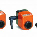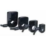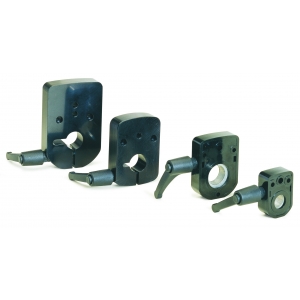
Main Features:
- Locking flange for OP/EP position indicators OP2, OP3, OP5, OP6, OP7, EP7, OP9.
- Provides clamping to hold a shaft in position, preventing movement under vibration or light loads.
- Tight fitment against OP body for added contamination resistance.
- Various metric and imperial bore hole sizes.
- Clamp handle position is reversible by customer.
- Technopolymer construction with aluminum clamp block.
On request:
- Metric and imperial bore hole sizes not shown on data sheet.
- ‘IN’ stainless steel clamp block option.
- Clamp handle position can be ordered on right (standard) or left (optional) side of flange.
- Locking flange for EP position indicators EP9L, EP20, EP25L, EP43NET – EP46NET, EP43RS – EP46RS, F43-46RS with EM43-46, EP43RS – EP46RS
Product features
| Range | OP2, OP3, OP5, OP6, OP7, EP7, OP9, EP9L, EP20, EP25L, EP43NET – EP46NET, EP43RS – EP46RS, F43-46RS with EM43-46, EP43RS – EP46RS |
|---|---|
| Construction | Technopolymer body, aluminum clamp (optional stainless) |
OP2
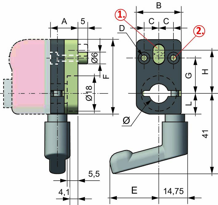
1. Bore for lock-pin Ø6
2. 2 fixing bores
| Type | Dimension | ||||||||||
| Ø | A | B | C | D | E | F | G | G1 | H | L | |
| OP5 | 20 | 18 | 52 | 18 | ø 4,5 | 57,5 | 74 | 20 | – | 30 | 25 |
| OP9 | 20-25 | 18 | 64 | 18 | ø 4,5 | 64 | 94 | 25 | 40 | 30 | 25 |
OP3 – OP6 – OP7
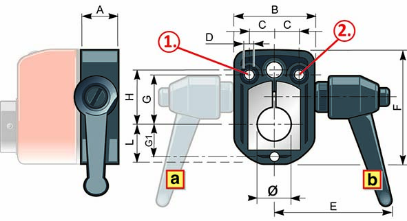
1. Bore for lock-pin Ø6
2. 2 fixing bores Ø
| Type | Dimension | ||||||||||
| Ø | A | B | C | D | E | F | G | G1 | H | L | |
| OP3 | 14-10 | 15 | 32 | 10 | ø 4,2 | 50 | 46 | 20 | – | 22 | 16 |
| OP6 – OP7 | 20-14 | 15 | 48 | 18 | ø 4,2 | 50 | 66 | 25 | 19,5 | 30 | 24 |
OP5 – OP9
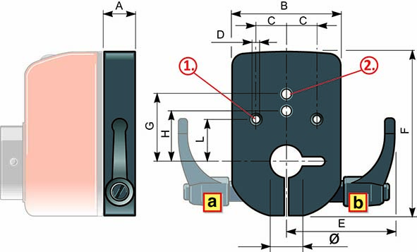
1. Bore for lock-pin Ø6
2. 2 fixing bores
3. Embedding ø17×1
| Type | Dimension | |||||||||
| Ø | A | B | C | D | E | F | G | H | L | |
| OP2 | 8-10-12 | 14 | 23 | 7,5 | ø 3,1 | 25 | 38 | 18 | 22 | 10,5 |

